I have been interested in the “Class E” audio amps & have purchased a few over the years to evaluate. In recent years a company called Sure Electronics has been offering many power amp modules that are attractive because of the low prices and high performance. And the black boards look cool. Parts Express sells a wide selection of these, so i decided to build an amp around one and see how well it would work. I had a nice surplus chassis sitting around, and along with a homebrew power supply, it seemed like a fun project.
I picked the Sure Electronics IRS2092, Parts Express 320-313 ($57 when i bought mine in May, 2014). This is an implementation of a reference design from International Rectifier Corp. called IRAUDAMP7D, by Jun Honda, Manual Rodriguez, and Wenduo Liu, published in Sep. 2008. My quotes here in are from Rev. 2.9 of this, published October 24, 2013.
The original IR design was “scalable” meaning different parts could be used in the same design for varying output power levels. This board implements the most powerful one, 2x250W non-bridgeable, i.e. Model AMP7D-200 in the original reference design document. It has the following specs:
- Power MOSFET: IRFI4020H-117P
- Controller IC: IRS2092
- Nominal and test supply voltage: +/- 70V
- Supply voltage: +/-60V minimum; +/-80V maximum
- Undervoltage protection threshold: 51V
- Overvoltage protection threshold: 91V
- PSRR: >50dB below 20kHz
- Voltage gain: 40
- Power output: 250W x2 into 8W load
- Bridging: supports half bridge mode only
Power supply
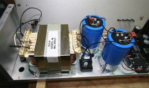
I used a center tap AC mains transformer surplused from an old Pioneer home theater receiver (circa late 1990’s) that i bought at a garage sale for $5 specifically for parts like this. This measured 47.4VAC open circuit with 118V input. This feeds a 25A/400V rated bridge, and a pair of 33,000uF 80V capacitors. (Why these cap values? Because 47VACx1.414=66VDC roughly, and good practice is to select a WVDC about 20% above actual working voltage, which is about 80V. [Hammond Manufacturing design note, p. 11, among others]. Another rule of thumb for audio amp, full-wave rectifier power supplies, is a capacitance of about 1,000uF per 10W rms. [Sloane]) Lacking appropriate caps in my junkbox, I browsed the selection at DigiKey, selecting 80V, anything above 22000uF, and sized to fit my chassis. This narrowed it down to a few models, from which i chose the one with the lowest ESR. This was part number 338-1986-ND, at $18.97 each, made by CDE, and rated for 13.37A ripple current.) The hot line input is fused with a 5A slo-blo, which i picked assuming a max current input at 117VAC should be about 4.2A when the amp is delivering 500W. With the amp connected, the power supply output was +64.2VDC and -64.1VDC, with 5.5mVrms and 7.5mVrms AC ripple on the buses, respectively.
The IRF ref design says it pulls a maximum of 7.5A at 70VDC; and pulls about 50mA at idle. In my testing i never popped the fuse.
Construction
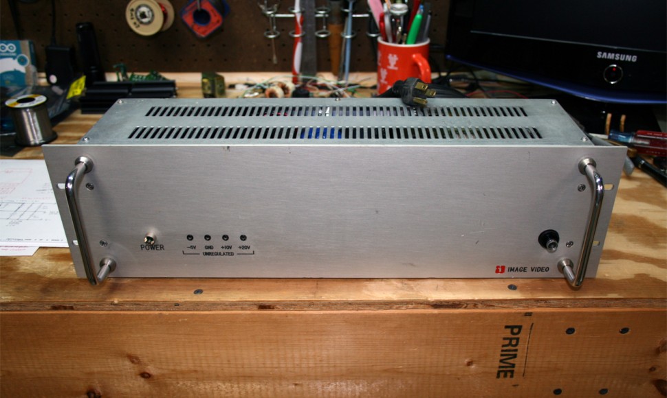
The packaging was determined by an old, rack-mount chassis i had on hand. It was a nice size for this project.
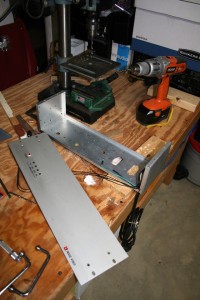
First gut the enclosure, and drill the holes needed to mount my parts.
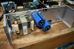
Mount the power supply components and connectors.
Wire up and test the power supply.
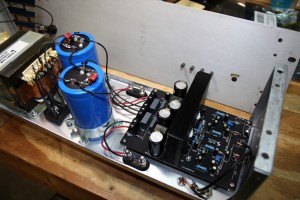
Mount and wire in the amplifier module.
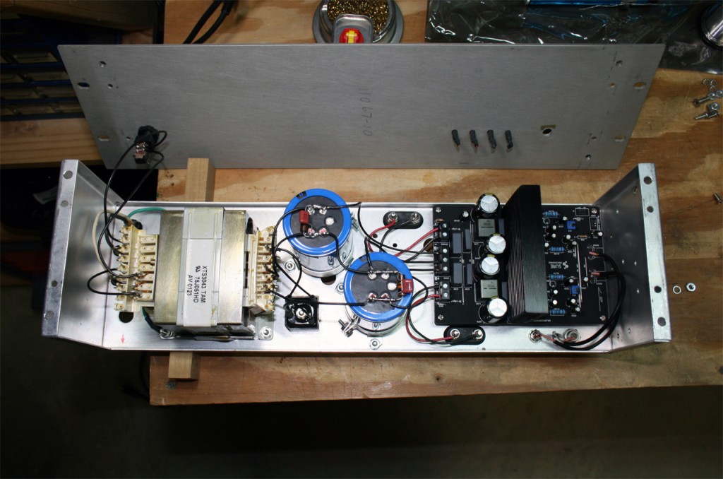
With the speaker terminals connected, the assembly is complete. The last step is to bolt on the front panel with the nice, 70’s style chrome rack handles.
Amplifier clock
The board as received from the factory was way off frequency. The left channel was measured at 329kHz, 3.3V p-p across the speaker. The right channel was 256kHz, 5.2Vpp across the speaker. I noted the output network was running very hot; the inductor was too hot to touch. The IR reference document says the amp was designed to operate at 400kHz for best performance. I adjusted the two pots on the board, which were flimsy and touchy. I set the L channel to 423kHz, and the R to 395kHz. That was as close as I could get them. The R channel clock then measured 2.0Vpp across the speaker, and the output inductor ran cooler.
Tests
Click here for a detailed test report of this amp as built (pdf file): Test of Sure Electronics amp
The main results are as follows:
- max power into 8 ohm load: 255W per channel
- gain: 30.2dB (both channels identical)
- max. input level for 1dB compression: 1.2V rms
- min. THD+N (A-weighted, 1kHz, into 4 ohms): 0.003%
- THD+N (A weighted, 1W into 4 or 8 ohms): 0.015%
- THD+N (A weighted, 10W into 4 or 8 ohms): 0.005%
- THD+N (A weighted, 100W into 4 ohms): 0.009%
- frequency response (-3dB, into 4 ohms): 5.5 – 38kHz
- S/N ratio: 86dB (or 100dB if limited by 1kHz lowpass filter)
- damping factor (at 1kHz, into 4 ohm load): 181
- (at 1kHz, into 8 ohm load): 303
For listening, I only had a few pairs of speakers to try this amp with. With the high clock output i didn’t want to connect it to any expensive speakers. But i had a set of 1990’s Paradigm Phantom speakers, that worked well. With certain types of music this combination sounded good. Unfortunately i didn’t have a good sub cabinet to try this on. I am designing a sub using 15″ drivers, and i expect this amp will work very well with that.
Conclusion
This amp met all published specs, except for overall gain, which was not important.
The main concern for long term use is the output inductor, which runs very hot to the touch, especially when the amp sits idle (i.e. nothing on the input). I think this will probably cause failure of the adjacent filter cap, since they are almost physically touching and will keep the cap at a constant, elevated temperature. The entire output load passes through this little inductor. The datasheet for this part says it is rated at 13.5A, which is fine but either it should be heatsinked or have a small blower fan for long life.
The included documentation with the amp is poor. It has contradictory information about the power supply voltage range, and omits listing the proper audio input levels, damping factor, the built-in switch feature, how the protection circuits recover, and how to set the oscillator frequency. If the original Infineon/IR document weren’t available on the web, the end user would probably have some real head scratching moments with this amp, if not a downright meltdown of it.
Everything about this amp suggests it would be excellent for driving a subwoofer. I would hesitate to use this amp for critical, audiophile listening in the rest of the audio band. Reasons include the potential of the switching frequency inter-modulating with program content, concerns about the “zobel” network on the output, and the under-damped performance above 1kHz. According to the reference design, there is extensive, integrated protection against shorts, over-driving, and power supply over and under voltage. (These features were not tested.) And of course the high efficiency (>80%) is very helpful when driving a large sub at 100W or higher levels.
In all, this was a lot of fun to put together and experiment with.
1 Comment
James
June 6, 2017 - 7:42 amThanks for the test report! Been using this amp for a while and had wondered about what the published specs left out.